B.Tech. I & II Semester
Examination, November 2022
Grading System (GS)
Max Marks:
70 | Time: 3 Hours
Note:
i) Attempt any five questions.
ii) All questions carry equal marks.
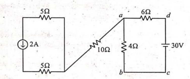
a) Find the voltage $V_{ab}$ in the network shown below. (Unit 1)
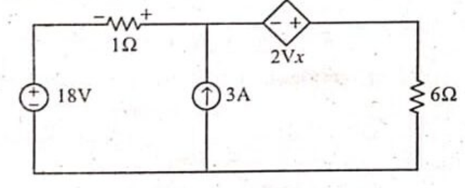
b) Find the current through the $6 \Omega$ resistor using Thevenin's theorem. (Unit 1)
a) Draw Phasor diagrams of the following circuits. (Unit 2)
i) Series R-L-C when $X_L > X_C$
ii) Series R-L-C when $X_L < X_C$
iii) Series R-L-C when $X_L = X_C$
b) A 3-$\phi$ balanced system supplies 110V to a delta connected load whose phase impedance is equal to $(3.54+j3.54)\Omega$. Determine the line currents and draw the Phasor diagram. (Unit 2)
a) Draw Phasor diagram of a 3-phase delta connected load and find the relation between phase and line voltages and currents. (Unit 2)
b) A 220 V, 100 Hz, A.C source supplies a series RLC circuit with a capacitor and a coil. If the coil has 50 mH inductance, find at a resonance frequency of 100 Hz, what is the value of capacitor? (Unit 2)
a) Draw the typical normal magnetization curve of ferromagnetic material. (Unit 3)
b) Explain in detail the Applications of DC Machines. (Unit 4)
a) Draw and explain the output characteristic of a NPN transistor operation in CE configuration. (Unit 5)
b) The no-load ratio required in a single-phase 50 Hz transformer is 6600/600 V. If the maximum value of flux in the core is to be about 0.08 Wb, find the number of turns in each winding. (Unit 3)
a) Enumerate the various losses in a transformer. How these losses can be minimized? (Unit 3)
b) Explain the construction and working principle of three-phase induction motor with suitable diagram. (Unit 4)
a) What is the difference between a separately excited and a self-excited generator? (Unit 4)
b) An 8-pole DC machine has a wave winding containing 600 conductors. Calculate the generated e.m.f when the flux per pole is 0.08 Wb and speed is 215 rpm. If the flux per pole is made 0.05 Wb. At what speed should the armature be driven to generate 5001V. (Unit 4)
Write short notes on: (any two)
a) R-S flip-flop (Unit 5)
b) J-K flip-flop (Unit 5)
c) De-Morgan's theorem (Unit 5)
d) Star Delta transformation (Unit 1)